Blog on embedded programming

The trip to the dark side

Stm32f4 General Purpose Timers Assembly Programming

Hello everyone ! This post introduces a very basic example of stm32f4 timers’ usage. We’re going to drive our four leds on stm32f4discovery with four general purpose timers TIM2..TIM 5. All of them are used as 16 bit. The task is to let timers count their own period and TIM3..TIM5 timers’ periods are multiples of TIM2’s period. To distinguish that periods of blinking are correct I’ve chosen rather long values: 3, 6, 9 and 12 sec.

One more feature this post is different from previous ones - it’s code will not be 100% assembly. There is a post about plain gcc project template for stm32f4xx. So the concept is to write those things in assembly we want to focus on. You’ll need the possibility to compile together with the ST library to get the code in this post working. For more info please refer to the link I provided above for you.

Making stm32f4 timer to count is simple enough. Let’s look at the main.c code first

(main.c) download
1
2
3
4
5
6
7
8
9
10
11
12
13
14
15
16
17
18
19
20
21
22
23
24
25
26
27
28
29
30
31
32
33
34
35
36
37
38
39
40
41
42
43
44
45
46
47
48
49
50
51
52
53
54
55
56
57
58
59
60
61
62
63
64
65
66
67
68
69
70
71
72
73
74
75
76
77
78
79
80
81
82
83
84
85
86
87
88
89
90
91
92
93
94
95
96
97
98
99
100
101
102
103
104
105
106
#include  "stm32f4_discovery.h"

extern void tim_2_init (void);
extern void tim_3_init (void);
extern void tim_4_init (void);
extern void tim_5_init (void);

void gpio_init (void);
void rcc_init (void);
void nvic_init (void);
void flash_green (void);
void flash_orange (void);
void flash_blue (void);
void flash_red (void);


/**
 * Main routine
 *
 * It consists of init stage and an endless loop.
 * Everything else is done in interrupts handlers,
 * which are in assembly
 * In this routine we enable peripherals' clock for timers and port,
 * setting up port D, globally enabling interrupts in NVIC
 * and initializing each timer
 */
int main (void)
{
    rcc_init ();
    gpio_init ();
    nvic_init ();
    tim_2_init ();
    tim_3_init ();
    tim_4_init ();
    tim_5_init ();

    while (1)
        ;

    return 0;
}

/**
 * Port D initialization
 *
 * Setting up pins 12-15 (with LEDS) as outputs
 */
void gpio_init ()
{
    GPIO_InitTypeDef gpio_init;
    gpio_init.GPIO_Pin = GPIO_Pin_12 | GPIO_Pin_13 | GPIO_Pin_14 | GPIO_Pin_15;
    gpio_init.GPIO_Mode = GPIO_Mode_OUT;
    gpio_init.GPIO_Speed = GPIO_Speed_100MHz;
    gpio_init.GPIO_OType = GPIO_OType_PP;
    gpio_init.GPIO_PuPd = GPIO_PuPd_NOPULL;

    GPIO_Init (GPIOD, &gpio_init);
}

/**
 * Peripherals' clocks initialization
 *
 * Enabling clock for timers (APB1 bus) and port D (AHB1)
 */
void rcc_init ()
{
    RCC_APB1PeriphClockCmd (RCC_APB1Periph_TIM2 | RCC_APB1Periph_TIM3 |
                            RCC_APB1Periph_TIM4 | RCC_APB1Periph_TIM5,
                            ENABLE);
    RCC_AHB1PeriphClockCmd (RCC_AHB1Periph_GPIOD, ENABLE);
}

/**
 * Interrupts global enable
 */
void nvic_init ()
{
    NVIC_EnableIRQ (TIM2_IRQn);
    NVIC_EnableIRQ (TIM3_IRQn);
    NVIC_EnableIRQ (TIM4_IRQn);
    NVIC_EnableIRQ (TIM5_IRQn);
}

/**
 * Following routines are called from each timer interrupt
 * handler
 */
void flash_green ()
{
    GPIO_ToggleBits (GPIOD, GPIO_Pin_12);
}

void flash_orange ()
{
    GPIO_ToggleBits (GPIOD, GPIO_Pin_13);
}

void flash_blue ()
{
    GPIO_ToggleBits (GPIOD, GPIO_Pin_15);
}

void flash_red ()
{
    GPIO_ToggleBits (GPIOD, GPIO_Pin_14);
}

Well, the most useful stuff about timers is hidden from the code above. One of the most important things to know about timers is how to determine exact time which it takes to count for one period. Let’s do little math.

In general to set timer counting period time we need to know the time period of a timer clock signal and to set apropriate value for timer reload register. Timer will count until that value is reached and as a result wait exactly needed time before executing the interrupt handler. Here we’re talking about basic upcounting mode (the default one), but stm32f4 timers are rather flexible and need a bunch of posts to cover their functionality.

Let’s discover how the system clock frequency becomes the frequency of a timer clock signal. So we need to refer to the user manual’s chapter on RCC and here is a figure there which will help us:

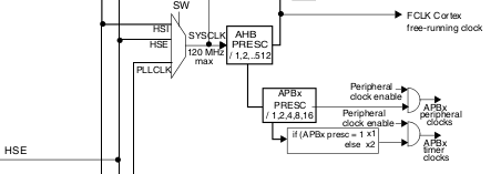
Timers source their clocks from “APBx timer clocks” point. Note the block which doubles clock’s signal frequecy if APBx prescaler’s factor is greater than 1. For example while we were speeding up stm32f4discovery to 168MHz, these prescaling factors were APB1 PRESC = 4, APB2 PRESC = 2 and AHB PRESC was 1. Timers TIM2..TIM5 are on APB1 bus. So, in that case the timers’ clock frequency:

ftim = ((168MHz / 1) / 4) * 2 = 2 * 168MHz / 4 = 168MHz / 2 = 84MHz

Well, the good news are that timer also has a prescaler. For example let’s assume that we need 3sec timer count period. If we’ll set maximum reload value for 16bit: 0xFFFF or 65535. Without a prescaler on ftim frequency the maximum timer period could be reached is:

T = (65535 + 1) / 84MHz = 0.00078 sec.

Timer prescaler allows to divide ftim with up to 0xFFFF + 1 factor and rather long delays can be reached. So, knowing the delay value and the timer clock frequency value we still need to figure out two parameters: a preload value, a timer prescaler value. To achieve accurate delay value these parameters should be a proper combination of two whole numbers.

To solve the problem we need to solve the following system of equations:

delay = (Nreload + 1) / fpresc;
fpresc = ftim / (Npresc + 1).

Next script in python shows the principle of how this could be done:

(tim_2_5.py) download
1
2
3
4
5
6
7
8
9
10
11
12
13
14
#!/usr/bin/env python

Ftim = 84e6
delay = 3

Npresc = Nreload = 0
fract = -1

while fract <> 0 or Npresc > 0xffff:
    Nreload = Nreload + 1
    Npresc = delay * Ftim / (Nreload + 1) - 1
    fract = Npresc - int(Npresc)

print "Npresc = %d\nNreload = %d" % (Npresc, Nreload)

Well, in this post I initialize all four TIM2..TIM5 timers to count 3, 6, 9 and 12 seconds respectively and toggle LEDs.

Here is the code in assembly which does that thing. I simplified code as all the initialization are the same between TIM2..TIM5 timers:

(tim_stripped.S) download
1
2
3
4
5
6
7
8
9
10
11
12
13
14
15
16
17
18
19
20
21
22
23
24
25
26
27
28
29
30
31
32
33
34
35
36
37
38
39
40
41
42
43
44
45
46
47
48
49
50
51
52
53
54
55
56
57
58
59
60
61
62
63
64
65
66
67
68
69
70
71
72
73
74
75
76
77
78
79
80
81
82
83
84
85
86
87
88
89
90
91
92
93
94
95
96
97
98
99
100
101
102
103
104
105
106
107
108
109
110
111
112
113
114
115
116
117
118
119
120
121
122
123
124
125
126
127
128
129
130
131
132
133
134
135
136
137
138
139
140
141
    .thumb
    .cpu        cortex-m4
    .syntax     unified

    .equ        TIM2_BASE, 0x40000000
    .equ        TIM2_ARR,  TIM2_BASE + 0x2C
    .equ        TIM2_CR1,  TIM2_BASE
    .equ        TIM2_DIER, TIM2_BASE + 0x0C
    .equ        TIM2_PSC,  TIM2_BASE + 0x28
    .equ        TIM2_SR,   TIM2_BASE + 0x10
    .equ        TIM2_EGR,  TIM2_BASE + 0x14

    /*
    ---------- TIM3..TIM5------------------
    */

    .equ        CEN, 1
    .equ        UIE, 1
    .equ        UIF, 1
    .equ        UG,  1

    .globl      tim_2_init
    .globl      TIM2_IRQHandler
    .globl      tim_3_init
    .globl      TIM3_IRQHandler
    .globl      tim_4_init
    .globl      TIM4_IRQHandler
    .globl      tim_5_init
    .globl      TIM5_IRQHandler


.section        .text
    .type       tim_2_init, %function
tim_2_init:
    push        {r0, r1}
    ldr         r0, =TIM2_ARR               /* preloading count value */
    movw        r1, 3999
    str         r1, [r0]

    ldr         r0, =TIM2_DIER              /* enabling update interrupt */
    ldr         r1, [r0]
    orr         r1, UIE
    str         r1, [r0]

    ldr         r0, =TIM2_PSC               /* setting timer clock prescaler */
    movw        r1, 62999
    str         r1, [r0]

    ldr         r0, =TIM2_EGR               /* update event to apply prescaler*/
    ldr         r1, [r0]
    orr         r1, UG
    str         r1, [r0]

    ldr         r0, =TIM2_CR1               /* enabling counter */
    ldr         r1, [r0]
    orr         r1, CEN
    str         r1, [r0]

    pop         {r0, r1}
    bx          lr
    .size       tim_2_init, . - tim_2_init


    .type       TIM2_IRQHandler, %function
TIM2_IRQHandler:
    push        {r0, r1, lr}
    bl          flash_green
    ldr         r0, =TIM2_SR                /* clearing interrupt flag */
    ldr         r1, [r0]
    bic         r1, UIF
    str         r1, [r0]

    pop         {r0, r1, lr}
    bx          lr
    .size       TIM2_IRQHandler, . - TIM2_IRQHandler


    .type       tim_3_init, %function
tim_3_init:
    /*
    ---------TIM3
    */
    .size       tim_3_init, . - tim_3_init


    .type       TIM3_IRQHandler, %function
TIM3_IRQHandler:
    push        {r0, r1, lr}
    bl          flash_orange
    ldr         r0, =TIM3_SR                /* clearing interrupt flag */
    ldr         r1, [r0]
    bic         r1, UIF
    str         r1, [r0]

    pop         {r0, r1, lr}
    bx          lr
    .size       TIM3_IRQHandler, . - TIM3_IRQHandler


    .type       tim_4_init, %function
tim_4_init:
    /*
    ------------ TIM4--------------------
    */
    .size       tim_3_init, . - tim_3_init


    .type       TIM4_IRQHandler, %function
TIM4_IRQHandler:
    push        {r0, r1, lr}
    bl          flash_red
    ldr         r0, =TIM4_SR                /* clearing interrupt flag */
    ldr         r1, [r0]
    bic         r1, UIF
    str         r1, [r0]

    pop         {r0, r1, lr}
    bx          lr
    .size       TIM4_IRQHandler, . - TIM4_IRQHandler


    .type       tim_5_init, %function
tim_5_init:
    /*
    -------- TIM5 -------------------
    */
    .size       tim_5_init, . - tim_5_init


    .type       TIM5_IRQHandler, %function
TIM5_IRQHandler:
    push        {r0, r1, lr}
    bl          flash_blue
    ldr         r0, =TIM5_SR                /* clearing interrupt flag */
    ldr         r1, [r0]
    bic         r1, UIF
    str         r1, [r0]

    pop         {r0, r1, lr}
    bx          lr
    .size       TIM5_IRQHandler, . - TIM5_IRQHandler

The original source can be downloaded here.

If we were coding in plain assembly then we would give our own names to interrupt handlers. But in our gcc examples handlers are already declared in stm32f4xx_startup.S file. This file is located under STM32F4-Discovery_FW_V1.1.0/Libraries/CMSIS/ST/STM32F4xx/Source/Templates/TrueSTUDIO path in library version I have.

There is one more thing still remaining behind the scenes. The default system_stm32fxx.c file is configured for 25 MHz crystal for some reason - the value of a PLL_M constant is 25. It’s located under path STM32F4-Discovery_FW_V1.1.0/Libraries/CMSIS/ST/STM32F4xx/Source/Templates. If we don’t care about system clock frequency in our project - it’s OK. But if we do care like in the current case we need to change it.

In our gcc project workspace for stm32f4xx programming there is an option to use project’s own system_stm32f4xx.c file. Please refer to that post for details. To clear out the meaning of PLL_M value I recommend to read the post about stm32f4xx 168 MHz speed up. Here are my Makefile and system_stm32f4xx.c files for reference.

As we have 8 MHz crystal on board of stm32f4discovery, if PLL_M = 8 then the system clock is 168 MHz and the timer clock is 84 MHz and all the above calculations will give you accurate timer control. If something remains unclear on topic, don’t hesitate to ask questions. The binary for this post is available for download.